
















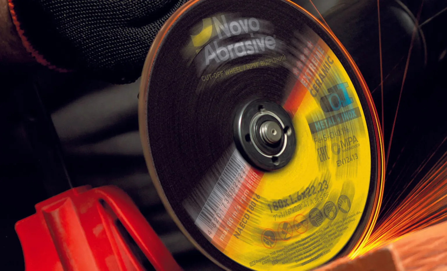
Replacing the cutting disc on a grinder may seem like a small thing, but this is where mistakes are most often made that affect the operator's safety and the tool's lifespan. Let's look at which side to put the disc on and why this is not an accident, but an engineering decision.
NovoAbrasive factory recommendation
When installing a cutting disc on an angle grinder (angle grinder, angle grinder, angle grinder), the question often arises: which side should the disc be installed on - with the metal ring facing the clamping nut or the support flange?
NovoAbrasive recommends installing metal cutting discs with the metal ring facing outwards - from the side of the clamping nut of the KSHM. This arrangement corresponds to the technological purpose of the metal ring and ensures correct load distribution in the disc mounting area.
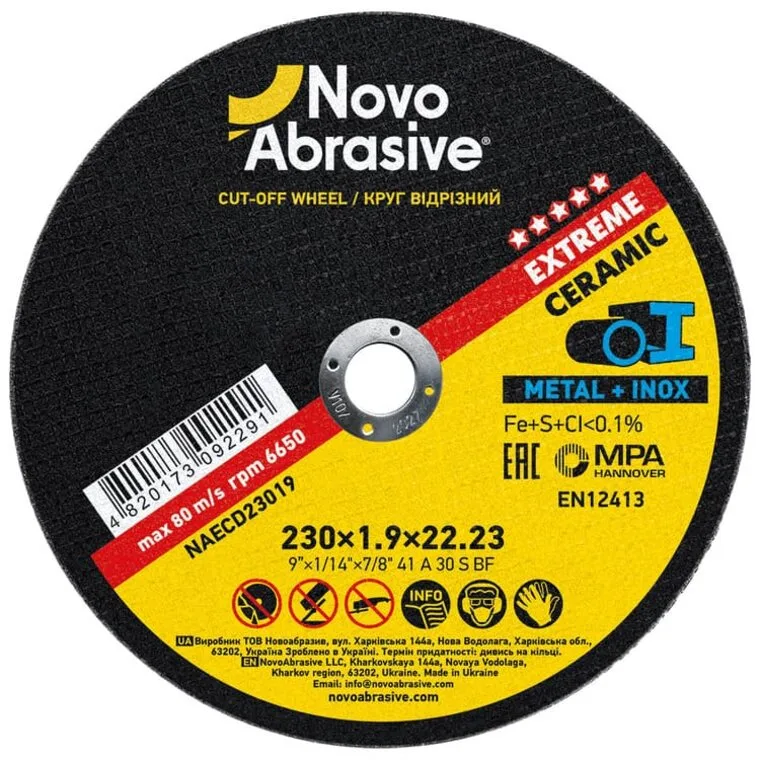
What is a metal ring for?
The cutting disc is a composite pressed under pressure and temperature: abrasive grain and fillers on a bakelite (phenolic) bond, reinforced with layers of fibre mesh. The material is strong against circumferential tearing, but brittle to local loads. The most loaded area of the disc is the bore, because it is through it that all the clamping force and torque reaction are transmitted.
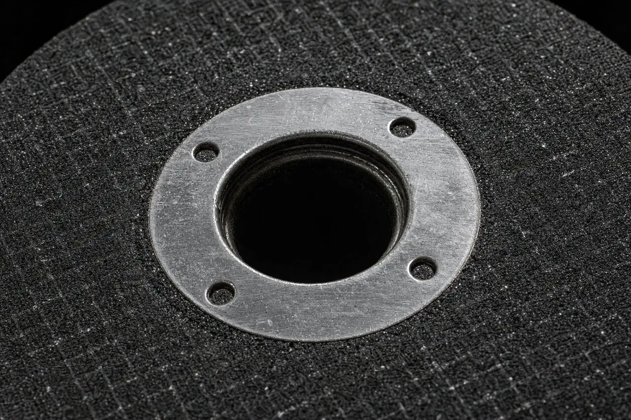
The metal ring performs four key functions:
- Seat hole reinforcement. Strengthens the central area of the disc during nut tightening, acceleration to operating speed, metal cutting, and under vibration and shock loads.
- Even distribution of clamping force. The clamping nut creates a significant axial load; the ring increases the contact area and distributes the pressure, protecting the fragile abrasive from local failure.
- Improved centering. The metal bushing helps the disc fit more precisely on the flange, reduces runout, and ensures stable operation at high speeds.
- Disc protection during installation. When the nut rests on a metal ring, the load is taken by the reinforced part of the structure, not the exposed abrasive.
Why is the disc placed with a ring to the nut?
The support flange (inner washer) is a wide, precise, flat metal surface that supports the exposed side of the abrasive well. Therefore, it is rational: the flat abrasive side rests on the wide flange, and the metal ring on the outside takes on a more concentrated force and torque from the nut.
Installation with a ring to the nut provides more reliable fixation, uniform distribution of tightening force, reduces the risk of chipping of the central part of the disc and the likelihood of the nut jamming after work, and also ensures stable operation of the tool at high speeds.
✓ Correct
- The metal ring is on the outside, towards the clamping nut.
- The flat abrasive side fits against the wide flange.
- The nut rests on a reinforced ring, not an abrasive.
- The direction arrow coincides with the spindle rotation.
✕ Error
- The ring is placed inside, against the flange.
- The nut presses directly on the brittle abrasive.
- Risk of chipping of the central area and uneven clamping.
- Beating and jamming of the nut, especially when the disc bites.
The role of the ring in production technology
The metal ring is inserted into the product during the production stage and after pressing becomes part of the disc's power structure. In simplified terms, the cycle looks like this:
- Formation of the bottom layer of abrasive mixture.
- Laying reinforcing fibre mesh.
- Installing the metal ring.
- Formation of the top layer of the mixture.
- High pressure pressing.
- Heat treatment and polymerization of the bond.
- Strength and balancing control.
That is why the ring is not a decorative element, but a structural part that should work in its normal position: outside, under the clamping nut.
Step-by-step installation instructions
- Disconnect the tool from the power supply - unplug the angle grinder or remove the battery.
- Check the disc - make sure there are no cracks, chips, and that the expiration date has not passed (stamping on the metal ring).
- Install the support flange on the spindle in its normal position.
- Place the disc with the metal ring facing outward, aligning the rotation direction arrow on the disc with the direction of rotation of the spindle.
- Tighten the spindle lock nut securely, but without excessive force.
- Run the tool at idle for 30–60 seconds, pointing it in a safe direction, to ensure there are no runs or hidden defects.
Ring side or direction arrow
The most critical safety parameter is the direction of rotation. The arrow on the disc must match the direction of rotation of the spindle. The ring side and the arrow are always checked together before each installation, and a short idle run is performed before operation.
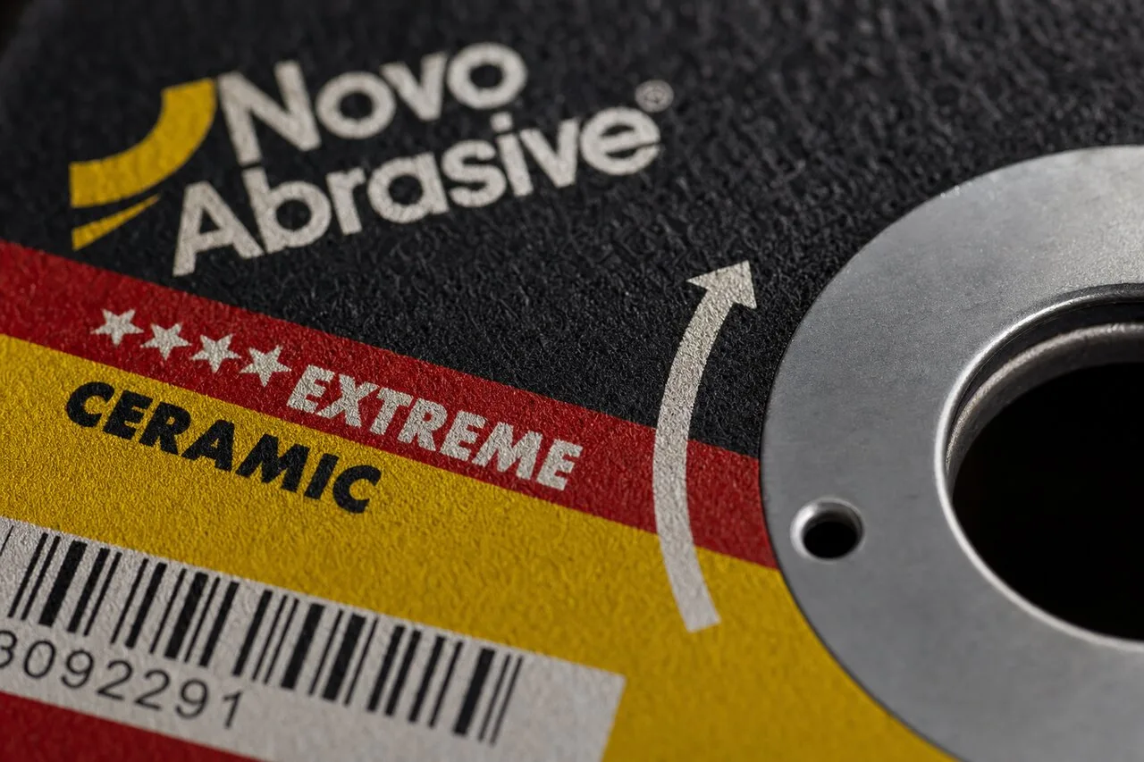
Before work, it is also useful to check the marking of the cutting disc according to EN 12413 and follow safety precautions when working with a grinder.
Frequently asked questions
Which side should I put the cutting disc on the grinder?
The metal cutting disc (type 41) is installed with the metal ring facing outwards - to the clamping nut of the KSHM. The smooth abrasive side is adjacent to the support flange.
Why is the metal ring on the cutting disc needed?
A metal ring reinforces the mounting hole, the most stressed area of the disc. It absorbs the force from the nut and torque, evenly distributes the clamping pressure, stabilizes the hole geometry and improves centering.
What happens if you install the disc with the ring inward (towards the flange)?
The nut will press directly on the brittle abrasive. This increases the risk of center chipping, uneven clamping, and chatter, especially when the disc bites at the end of a cut.
What is more important - the side of the ring or the direction of the arrow?
The direction of rotation is more critical. The arrow on the disc must match the direction of rotation of the spindle. The ring side and the arrow are checked together before each installation.
Does this recommendation apply to grinding discs?
The recommendation applies to flat cutting discs type 41. Recessed center grinding discs (type 27/42) have a different geometry and the orientation is determined by the hub design.
What is the standard size of the bore?
The most common standard is 22.23 mm (7/8"). The hole size must exactly match the spindle of the countersink.
Choose a NovoAbrasive cutting disc
Cutting discs for metal and stainless steel in three series - Standard, Profi and Extreme. Safety certification MPA Hannover.